Sylva Mojo

Hi, my name is Trevor, and here you can follow my build of a "Sylva Mojo" kit car. Please remember the oldest news is at the bottom of this page, so if you have not visited for a while, please read from the bottom up.

Sunday, February 25, 2007

Front hubs


Only managed a few hours of work today, but got both front hubs fully assembled.

This involved replacing both sets of brake disks and calipers with new items, and re fitting the steering arms, (sticking out lower left of photo.)

Saturday, February 24, 2007

Pedals Fitted


Today I fitted all the pedals, along with the brake and clutch master cylinders.

The pedals came with all the mounting brackets pre welded and drilled. The attention to detail is amazing, on photo four, you can see the way the brake pedal has been bent around where the steering column will sit. (Through where the hole in the panel is now.) Another example is on photo 1, you can see where the bracket has already been welded on to the brake pedal to accept the brake master cylinder arm. (Second item in with a nut and bolt through it)

Everything so far has fitted millimetre perfect, making for a thoroughly enjoyable build.

Monday, February 19, 2007

Rear hubs test fitted


Today I test fitted the two front hubs from the XR2 that are used on the rear of the Mojo.

The hub is turned upside down and attached to the lower wishbone bolt with a pair of strengthening spacer brackets. (Shown in pics 2, 3 and at the bottom of 4.)
The lower ball joint, (now at the top as the hub is inverted,) is secured onto the upper wishbone with two nuts and bolts. (Top of photo 4.)
Photo 4 also shows that the steering arm would have got in the way if not grinded off.

Everything will come back off again for a clean up, but this was a very successful test fitting of both rear hubs.

Sunday, February 18, 2007

XR2 Hubs Modified


The XR2 hubs and driveshafts are used at the rear of the Mojo, and as such need slightly modifying. The steering arm is not used as the hubs are "locked off" into facing forwards only, and the steering arms get in the way of the suspension. To eliminate this problem they are removed, in my case, with a cutting disk in an angle grinder. I had not used an angle grinder until today - what a frightening experience! Sparks flew just about everywhere in the shed, nothing caught fire - but I did have a bucket of water ready just in case!

I had managed to inadvertently damage the longer driveshaft cv joint whilst removing the engine and gearbox from the XR2, I now have a complete replacement ready, that’s the reason in the second photo why it has been removed.

Saturday, February 17, 2007

All wishbones fitted


Today I got the floor pan fully bonded and riveted on, then attached all the wishbones on the car.

Im really pleased with the F1 style inboard suspension, it looks even better than I thought it would! Once finished the inboard set up should give pin sharp handling.

The picture of the rear wishbones will be more self explanatory when the car is on its wheels and out of the garage – space is a bit limited in there to take good photos!

Friday, February 16, 2007

Floor pan prep


Today I drilled all the holes to attach the floor pan in the underside of the chassis, (car placed upside down,) and attached the two water tubes inside the tunnel.

As the Mojo is a rear engined car, two water tubes run along the inside of the tunnel, from the engine to the radiator at the front. By heating one of the tubes up with a mini blow torch, I was able to bend it upwards, so that the flexible tube run to the top of the radiator is made easier.

With every hole now drilled in the underside of the chassis, tomorrow I will bond and rivet the floor on, then the exciting bits of the build start – bolting parts onto the car!

Sunday, February 11, 2007

Paneling up


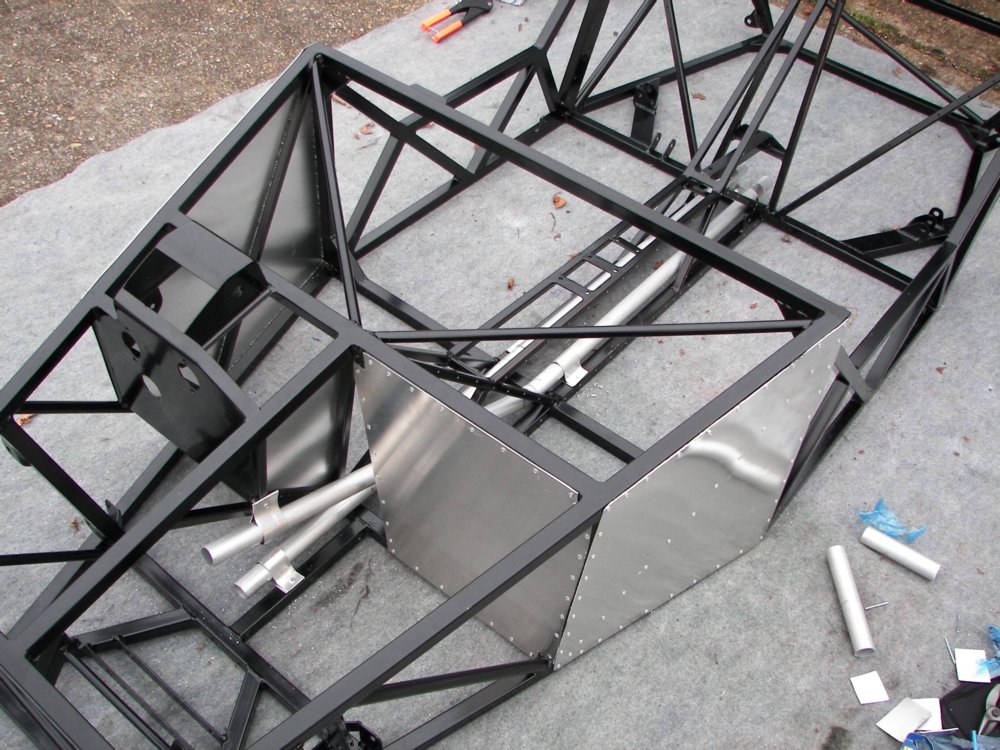
Today I fitted some of the ali panels to the Mojo.

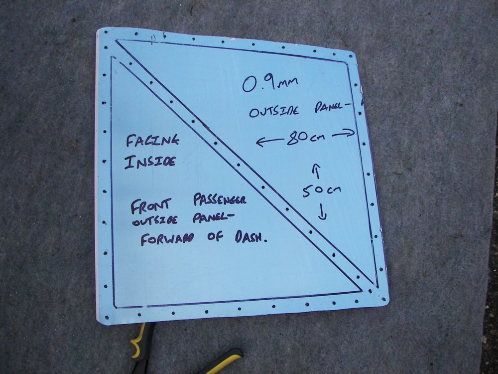
The top picture shows where I have marked the chassis onto the panel, then drilled through it. This panel was then deburred, placed back up to the chassis, and I drilled through the existing holes into the chassis – a scary moment! The second photo shows the chassis with the holes drilled in it.
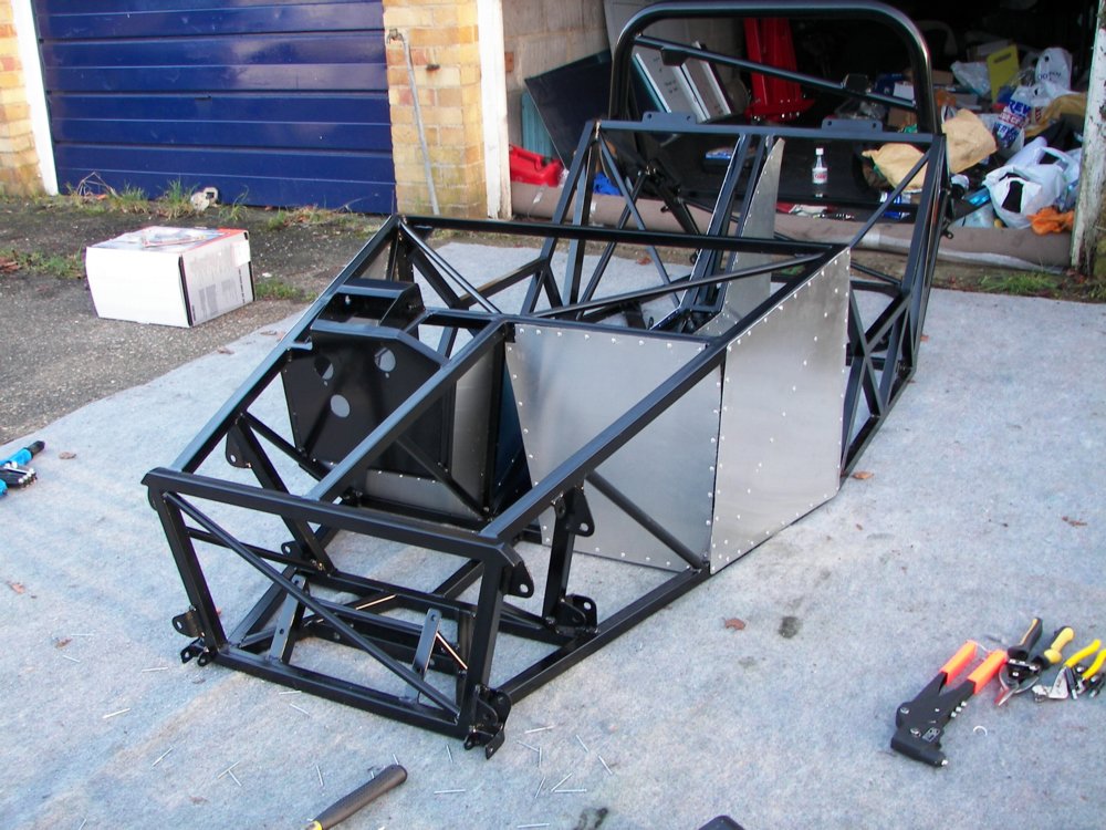
The panel then had its protective film removed, and was bonded using a polyurethane sealant and riveted into place.
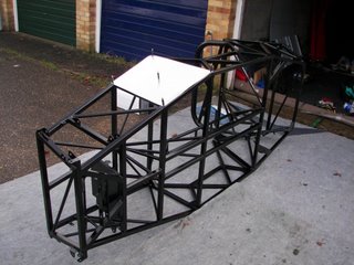
The easiest way of doing this was to put out some carpet down to protect the chassis, then turn it onto its side.

It was a good day all in all as I have now fitted the driver and passenger forward outer panels, the passenger foot well end panel and the two smaller panels that go under and to the left of the driver foot well area.

I have also drilled all the holes into the chassis to take the two tunnel side panels, but have not fitted them yet, as access is needed into the tunnel to fit brake lines, fuel pipes, water pipes……

The next job is to drill through the seat back panels into the chassis to mark out all the mounting holes. They will also not be fitted yet, as this makes access to installing the engine easier. Then I can fit the floor pan, a mini milestone!